Фрегаты типа Whitby
Основная информация
Главные размерения
Машина
- 2 * Babcock & Wilcox boilers
- 2 * English Electric steam turbines
- 2 * shafts
- 30,000 shp (22,000 kW)
Персонал
Боевые силы и средства
- Radar Type 293Q target indication (later Radar Type 993)
- Radar Type 277Q height finding (later removed)
- Radar Type 275 fire control on director Mark 6M
- Radar Type 262 fire control on STAAG
- Radar Type 974 navigation
- Type 1010 Cossor Mark 10 IFF
- Sonar Type 174 search
- Sonar Type 162 target classification
- Sonar Type 170 attack
- 1 * twin 4.5 in (114 mm) gun Mark 6
- 1 * twin 40 mm Bofors gun Mark 2 STAAG (later 1 * single 40 mm Bofors gun Mark 7)
- 2 * Limbo anti-submarine mortar Mark 10
- 12 * 21-inch (533 mm) anti-submarine torpedo tubes (removed or never shipped)
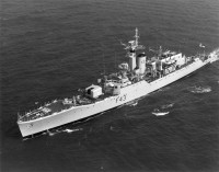
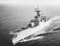
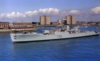
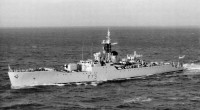
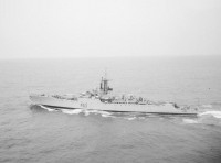
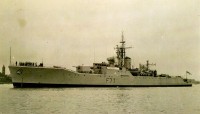
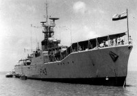
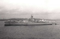
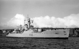
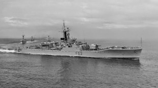
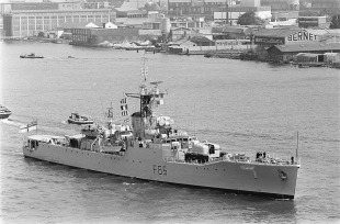
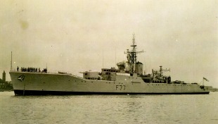
The Type 12 or Whitby-class frigates were a six-ship class of anti-submarine frigates of the British Royal Navy, which entered service late in the 1950s. They were designed in the early 1950s as first-rate ocean-going convoy escorts, in the light of experience gained during World War II. At this time, the Royal Navy were designing single-role escorts and the Whitbys were designed as fast convoy escorts capable of tackling high-speed submarines. However, this made the Whitbys more expensive and sophisticated to produce in large numbers in the event of a major war, and so the Type 14 «utility» or «second-rate» anti-submarine frigate was developed to complement the Type 12. Although themselves rapidly outdated, the Type 12 proved to be an excellent basis for a series of frigate designs used by the British and Commonwealth navies for the next 20 years.
Design
Critical to the design of the Type 12 was the capability to steam for long periods of time in heavy seas, economically and at high speed. For this reason a novel hull form was devised, which despite appearance, was totally unrelated to that of the earlier Type 41 / Type 61 design. The hull showed the fine lines more typical of a destroyer, but had a raised forecastle with considerable flare. The fo'c'sle deck was level to maintain maximum freeboard aft of the stem where it is most likely that waves will break across the deck. These two features meant that the hull not only cut through the water, but that spray was thrown upwards and outwards, away from the bridge and gun turret. This was especially important in high latitudes where war experience had shown that spray could cause rapid and undesirable ice build-up on the forecastle. The deck edges and hull also met at a curve rather than an angle, the anchors were recessed, and protrusions were kept to a minimum to limit the potential sources of ice build-up and spray generation. The Mark 6 gunhouse was large and heavy, so had to be carried low to maintain stability and give a good view over it from the bridge. The forecastle therefore had a very distinctive kink, allowing the position of the guns to be lowered. This had the added benefit of moving the bridge aft, where there was considerably less motion, improving the lot of the watchkeeper. The hull form, coupled with a twin-shaft double-reduction geared steam turbine plant (the Y-100) that operated at high temperature and pressure (for efficiency) and low revolutions, with new five-bladed low-cavitation propellers (for efficiency and quietness) lent themselves to the perfect hull for a high-speed, all-weather anti-submarine vessel.
Experience with the Type 15 frigate program, rebuilding wartime destroyers into fast anti-submarine frigates had led to the adoption of a bridge design characteristic of Royal Navy escorts up to the Leander class of 1969. The covered bridge, where the ship was conned, was located above the operations room where the ship was fought, and there was a small pilot's position located to the front of the bridge, giving the indicative «T» shape when viewed from above. Whitby was unique in that her bridge face was vertical, her sisters having the windows mounted at an angle to the face, to cut down on internal reflections inside the bridge in low-light. There was also an open navigation bridge located above and behind the enclosed one.
The original funnel was a straight, cylindrical affair that was designed to resist a nuclear blast, but this was prone to down-draughting and did not clear the hot exhaust gasses particularly well. It was replaced by a heightened, raked, streamlined version with a characteristic domed top. This was incorporated in later build vessels, and in all of the subsequent Rothesay class. Only Scarborough retained the stubby vertical funnel throughout her career.
Armament
The armament was based around two Limbo Mark 10 anti-submarine mortars. This allowed a three-bomb salvo to be placed both above and below the target, creating a convergent pressure wave more likely to assure a kill. The Limbos were mounted in a well on the quarterdeck, with a 360° arc of fire. Again, wartime experience had shown that the quarterdeck, perhaps not an obvious location for an ahead throwing weapon, was indeed the best location for such weapons where they were out of the spray towards the front of the vessel. The Limbo mortars were controlled by three sonars, the Type 174 search set, Type 162 target classification set and the Type 170 'pencil beam' targeting set. The lattice foremast carried the radar Type 293Q target indication set and the Type 974 navigation set, and a Type 277Q height finder was carried on a stump mast between the bridge and the mainmast. These sets were all derived from units of Second World War vintage.
Carrying the Limbos aft allowed the forecastle to be left clear for the twin 4.5in Mark 6 gun for anti-surface and limited anti-aircraft fire, controlled by a Mark 6M director with radar Type 285 mounted behind the bridge. Further anti-submarine capability was to be afforded by twelve 21 inch Mark 20E «Bidder» anti-submarine homing torpedoes, carried in fixed tubes; Four pairs were fixed firing forward on either beam, with a trainable pair behind these on each side. Ultimately the E version of the Mark 20 torpedo was a failure as it was not nearly fast enough to catch its intended target, and the tubes were removed (where they were fitted at all) and the torpedoes never deployed.
Self-defence against aircraft was provided by the elaborate STAAG weapon, a complex and ultimately failed exercise in engineering. The STAAG, or Stabilised Tachymetric Anti-Aircraft Gun, consisted of a two Bofors 40 mm L/60 guns, the radar Type 262 fire control set and a tachymetric computer. All this was carried on a common, stabilised, powered-operated gun mounting. Intended to function much as the modern CIWS does, this weapon was ahead of the limits of technology at the time and was overweight, overly complex and its sensitive valve electronics were a maintenance nightmare. Ultimately STAAG would be replaced by a simple and ubiquitous Bofors 40 mm gun on the single Mark 7 mounting.
Корабли8
- Комментарии
 ru
ru en
en uk
uk
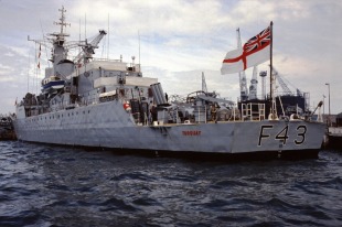
 Королевские военно-морские силы Новой Зеландии
 Королевский военно-морской флот Великобритании
 Военно-морские силы Индии